
Fundamentals of Inductively Coupled Plasma Mass Spectroscopy and How It Compares
According to the formal IUPAC definition of ICP-MS, the technique combines an inductively coupled plasma as an ionization source with a mass spectrometer as the analytical detector. Unlike optical emission methods that detect emitted light, ICP-MS measures the actual mass-to-charge ratio ($m/z$) of generated positive ions.
The process begins by introducing the sample aerosol into an atmospheric argon discharge. The high-energy plasma efficiently desolvates, vaporizes, atomizes, and ionizes the constituents of the sample. The resulting positive ions are then transferred from atmospheric pressure through a differentially pumped vacuum interface into the mass analyzer, where they are filtered and quantified.
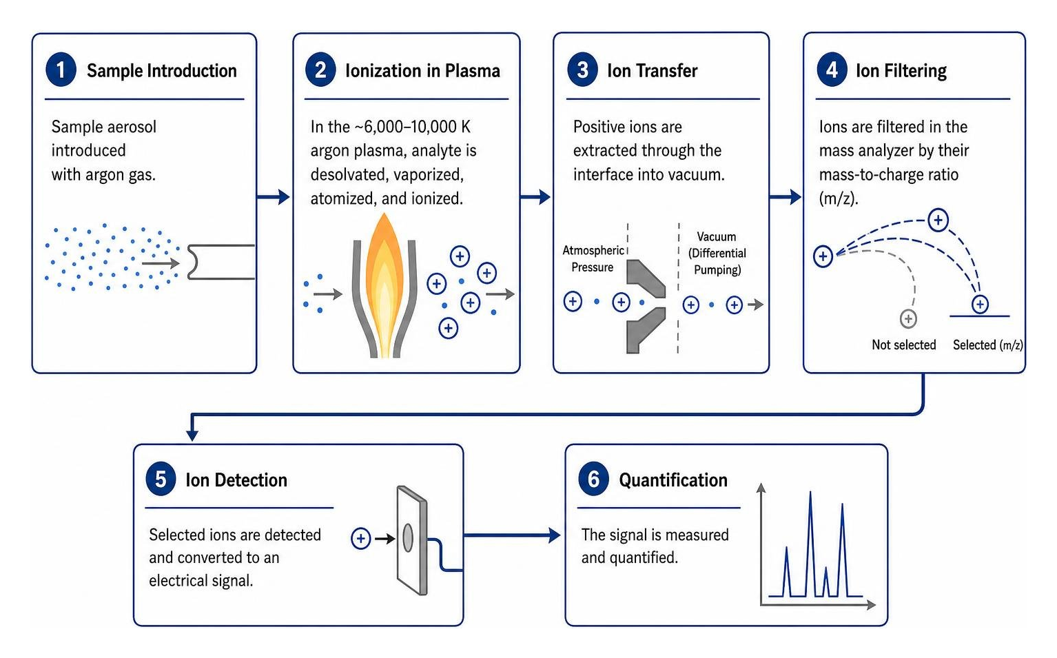
The Core Physics: Ionization in a 10,000 K Plasma
The heart of the system is the plasma torch surrounded by a copper radio-frequency (RF) load coil. Radio-frequency power (typically 1000 to 1600 W at 27 or 40 MHz) couples inductively with a continuous flow of argon gas (13 to 18 L/min). A spark initiates spark-ionization, seeding electrons that oscillate rapidly in the alternating magnetic field, colliding with argon atoms and sustaining an ionized gas reaching temperatures between 6,000 K and 10,000 K.
At these temperatures, analyte atoms undergo rapid thermal atomization followed by electron stripping. Because the first ionization potential of argon is 15.76 eV, it can effectively ionize nearly every element in the periodic table (from lithium at $m/z 7$ to uranium at $m/z 238$ and beyond), predominantly creating singly charged positive ions ($M^+$). Understanding how atoms are ionized in plasma fire is fundamental to optimizing RF power and nebulizer gas flow rates for maximum ion yield without generating excess oxide ions ($MO^+$).
Comparing Inductively Coupled Plasma Mass Spectroscopy to Optical Techniques (ICP-OES and AAS)
When evaluating atomic spectroscopy platforms, laboratories frequently assess ICP-MS alongside Inductively Coupled Plasma Optical Emission Spectrometry (ICP-OES) and Atomic Absorption Spectroscopy (AAS). While ICP-OES and AAS rely on optical emissions and photon absorption wavelengths, ICP-MS measures physical atomic particles.
| Analytical Parameter | Flame / Graphite Furnace AAS | ICP-OES (Optical Emission) | ICP-MS (Mass Spectrometry) |
|---|---|---|---|
| Detection Limits | Flame: ppm ($mu$g/mL) GFAAS: ppb ($mu$g/L) |
Sub-ppb to ppb ($0.1–10 mutext{g/L}$) | Sub-ppt to ppt ($<0.001–0.1 mutext{g/L}$) |
| Dynamic Linear Range | $10^2$ to $10^3$ | $10^5$ to $10^6$ | $10^9$ to $10^{12}$ |
| Sample Throughput | Sequential (1 element at a time) | Simultaneous ($>70$ elements in 1 min) | Rapid sequential/simultaneous ($>70$ elements in 1–2 min) |
| Total Dissolved Solids (TDS) | High tolerance (up to 5–10%) | High tolerance (up to 10–25%) | Low tolerance ($<0.2%$ w/v recommended) |
| Isotopic Analysis | No | No | Yes (measures individual isotopes) |
| Interferences | Chemical and spectral | Spectral line overlaps | Isobaric and polyatomic ion overlaps |
For laboratories evaluating trace limits versus matrix load, choosing between ICP-OES and ICP-MS often hinges on whether target analytes require parts-per-trillion sensitivity or if the sample matrix contains high levels of dissolved salts.
Anatomy of an ICP-MS: From Sample Introduction to Ion Detection
An ICP-MS instrument bridges atmospheric sample ionization with high-vacuum mass separation ($10^{-5}$ to $10^{-7}$ Torr) through a sequence of precisely engineered stages:
- Sample Introduction: Liquid delivery, aerosol conversion, and droplet filtering.
- Plasma Source: Ion generation in the argon discharge.
- Vacuum Interface: Ion extraction across sampling and skimmer cones.
- Ion Optics: Electrostatic focusing and neutral-species rejection.
- Collision/Reaction Cell: Attenuation of molecular and polyatomic overlaps.
- Mass Analyzer: Mass-to-charge separation.
- Detector: Discrete dynode conversion of ions into measurable electrical pulses.
Sample Introduction and Aerosol Generation
Liquid samples are introduced at flow rates typically between 0.1 and 1.0 mL/min using a peristaltic pump. The liquid reaches a pneumatic nebulizer (concentric, cross-flow, or micro-concentric), where high-velocity argon gas shears the liquid stream into a fine mist.
This mist enters a spray chamber (such as a double-pass or cyclonic design). The spray chamber acts as a low-pass filter, removing droplets larger than approximately 5 to 10 $mu$m. Only roughly 1% to 2% of the original sample reaches the plasma torch as a uniform aerosol; the remaining 98% drains to waste. This filtration prevents plasma cooling and localized thermal instability.
The Plasma Torch and Atmospheric Interface
The aerosol passes through the central injector of a quartz torch, surrounded by auxiliary and outer gas flows. Once ionized, the central channel of the plasma impinges directly onto the interface region, which must transition ions from atmospheric pressure (760 Torr) to a high vacuum.
This extraction occurs across two or three precision-machined metal cones (typically nickel or platinum):
- Sampler Cone: Has a typical orifice diameter of 0.8 to 1.1 mm. The plasma gas flows directly against this water-cooled cone, allowing the central channel of the ion stream to expand into a rough-vacuum region (1–3 Torr).
- Skimmer Cone: Positioned behind the sampler cone with a smaller orifice (0.4 to 0.7 mm). It skims the central portion of the expanding supersonic jet (the “zone of silence”) and directs it into the high-vacuum ion optics compartment.
- Hyper-Skimmer (in three-cone systems): Provides an intermediate extraction stage, reducing beam divergence and minimizing maintenance on downstream optics.
Detailed operational procedures regarding argon plasma spectrometry hardware outline how precise mechanical alignment and torch position preserve cone longevity and maximize ion transmission.
Ion Optics, Mass Analyzers, and Detectors
Once ions enter the high-vacuum region, electrostatic ion lenses bend and focus the positively charged ion beam while deflecting neutral atoms, non-ionized particulates, and photons away from the mass analyzer. Deflecting photons is critical because they can strike the detector and generate high background noise.
The focused ion beam enters the mass analyzer, commonly a quadrupole mass filter composed of four parallel molybdenum or stainless-steel rods. By applying combined direct current (DC) and radio-frequency (RF) voltages, the quadrupole establishes a time-dependent hyperbolic electric field. Only ions with a specific $m/z$ maintain a stable trajectory through the rods to reach the detector; all other ions collide with the rods or are pumped away. Modern quadrupoles can scan across the entire mass spectrum ($m/z 6$ to 260) at speeds exceeding 5,000 atomic mass units per second (amu/s).
Upon exiting the analyzer, ions strike an electron multiplier or discrete dynode detector. Each ion collision releases secondary electrons, cascading through dynode stages to generate an amplified current pulse that converts individual ion arrivals into counts per second (CPS).
Overcoming Interferences: Spectral and Non-Spectral Challenges
Accurate analysis requires identifying and mitigating both spectral (spectroscopic) and non-spectral interferences. Standard analytical protocols, such as EPA Method 6020B criteria, establish specific quality assurance mechanisms to detect and resolve these interferences in environmental and waste matrices.
Mitigating Isobaric and Polyatomic Spectral Overlaps
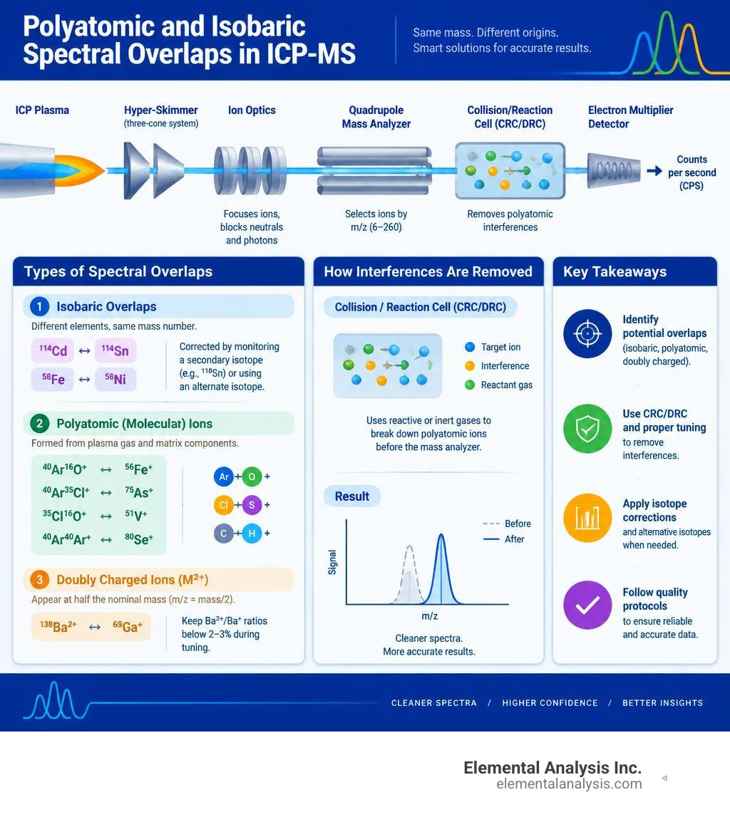
Spectral interferences occur when an unwanted ion shares the same nominal mass-to-charge ratio as the target analyte isotope. These fall into several categories:
- Isobaric Overlaps: Two distinct elemental isotopes share the exact same mass number. For instance, $^{114}text{Cd}$ overlaps with $^{114}text{Sn}$, and $^{58}text{Fe}$ overlaps with $^{58}text{Ni}$. These are routinely corrected by monitoring an undisturbed secondary isotope of the interfering element (e.g., measuring $^{118}text{Sn}$ to calculate and subtract the $^{114}text{Sn}$ contribution) or by selecting an alternate analytical isotope.
- Polyatomic (Molecular) Ions: Formed by the recombination of plasma gas components (Ar, O, N, H) and sample matrix constituents (Cl, S, C, Na). Classic examples include:
- $^{40}text{Ar}^{16}text{O}^+$ overlapping on the primary iron isotope $^{56}text{Fe}^+$
- $^{40}text{Ar}^{35}text{Cl}^+$ overlapping on the monoisotopic arsenic $^{75}text{As}^+$
- $^{35}text{Cl}^{16}text{O}^+$ overlapping on $^{51}text{V}^+$
- $^{40}text{Ar}^{40}text{Ar}^+$ overlapping on $^{80}text{Se}^+$
- Doubly Charged Ions ($M^{2+}$): Elements with low second ionization potentials (such as barium or rare earth elements) form $M^{2+}$ species, which appear at half their nominal mass ($m/z = text{mass}/2$). For example, $^{138}text{Ba}^{2+}$ appears at $m/z 69$, directly overlapping with gallium ($^{69}text{Ga}^+$). Maintaining Ba$^{2+}$/Ba$^+$ ratios below 2–3% during routine tuning minimizes this effect.
Collision and Reaction Cell Technologies
Modern ICP-MS instruments use Collision/Reaction Cells (CRCs) placed immediately before the analytical mass filter to eliminate polyatomic interferences (Wilschefski & Baxter, 2019). These cells utilize pressurized multipole assemblies (such as hexapoles or octopoles) to target spectral interferences through two primary mechanisms:
- Collision Mode with Kinetic Energy Discrimination (KED): An inert collision gas (typically pure helium, $text{He}$) is introduced into the cell. Because polyatomic interfering ions (e.g., $^{40}text{Ar}^{35}text{Cl}^+$) have larger ionic radii and collision cross-sections than monatomic analyte ions (e.g., $^{75}text{As}^+$), they collide more frequently with helium atoms and lose substantially more kinetic energy. An energy barrier (retarding potential) at the cell exit deflects these lower-energy polyatomic species while allowing the higher-energy analyte ions to pass into the mass analyzer. Helium collision mode with KED is the standard approach for multi-element screening because it suppresses multiple polyatomic ions simultaneously without generating new matrix-derived adducts.
- Reaction Mode: Highly reactive gases (such as hydrogen $text{H}_2$, oxygen $text{O}_2$, ammonia $text{NH}_3$, or methane $text{CH}_4$) undergo rapid, selective gas-phase chemical reactions. This can neutralize interfering ions through electron transfer or shift analyte ions to a higher, interference-free mass channel. For example, oxygen reacts rapidly with $^{75}text{As}^+$ to form $^{75}text{As}^{16}text{O}^+$ at $m/z 91$, effectively clearing the interference from $^{40}text{Ar}^{35}text{Cl}^+$ at $m/z 75$.
Matrix Suppression and Internal Standardization Strategies
Non-spectral interferences, or matrix effects, stem from physical and chemical properties of the sample solution:
- Physical Interferences: High dissolved solids, solvent volatility, or high acid concentrations alter sample viscosity and surface tension, changing nebulization efficiency and droplet size distributions.
- Space-Charge Effects: In the ion optics region, the positive ion beam contains high concentrations of heavy matrix ions (such as $text{Pb}^+$ or $text{U}^+$). Electrostatic repulsion pushes lighter analyte ions (such as $text{Li}^+$ or $text{Be}^+$) out of the beam path, suppressing their transmission.
- Ionization Suppression: High concentrations of easily ionized elements (EIEs), such as sodium or potassium, lower the ionization temperature of the plasma, reducing the ionization efficiency of elements with high ionization potentials (such as As, Se, and Zn).
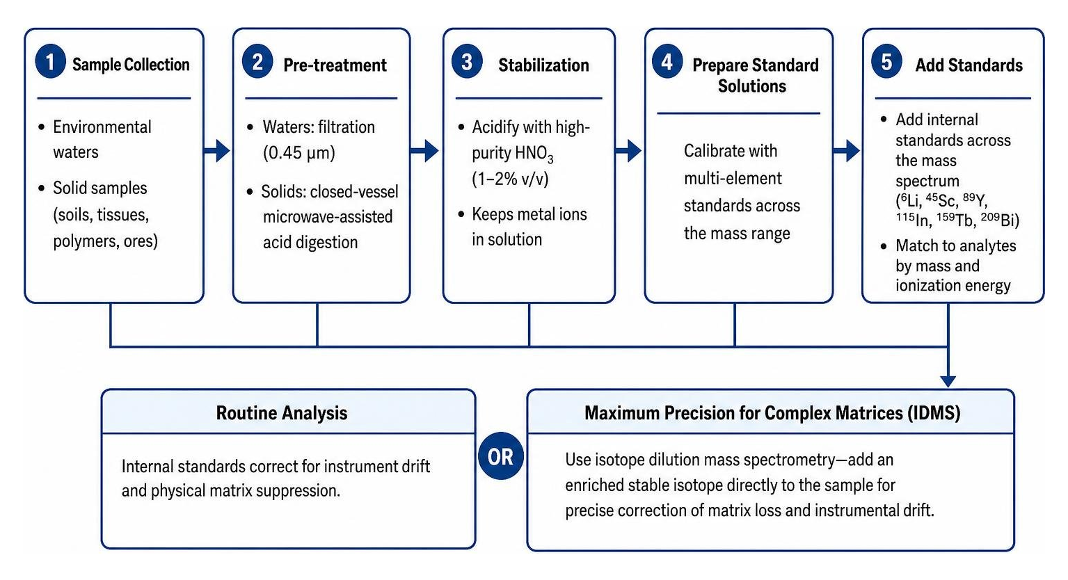
To correct for instrument drift and physical matrix suppression, analysts add internal standards across the mass spectrum (e.g., $^6text{Li}$, $^{45}text{Sc}$, $^{89}text{Y}$, $^{115}text{In}$, $^{159}text{Tb}$, and $^{209}text{Bi}$). The internal standard must be matched to analytes of similar mass and ionization energy. When maximum precision is required for complex matrices, isotope dilution mass spectrometry (IDMS)—which adds an enriched stable isotope directly to the sample—provides precise correction for matrix loss and instrumental drift.
Advanced Configurations and Sample Introduction Variants
While standard quadrupole systems handling liquid solutions address most routine applications, specialized configurations expand analytical capabilities for difficult matrices, solid samples, and ultra-trace detection.

High-Resolution, Sector-Field, and Tandem ICP-MS/MS Systems
- High-Resolution Sector-Field ICP-MS (HR-ICP-MS): Uses an electrostatic analyzer (ESA) paired with a magnetic sector analyzer. This configuration achieves resolving powers ($m/Delta m$) up to 10,000, physically separating isobaric overlaps from analyte peaks (such as separating $^{56}text{Fe}^+$ at 55.9349 Da from $^{40}text{Ar}^{16}text{O}^+$ at 55.9573 Da) without collision gases.
- Tandem ICP-MS (ICP-MS/MS or Triple Quadrupole ICP-MS): Incorporates two transmission quadrupoles separated by an octopole collision/reaction cell ($Q1text{–CRC–}Q2$). $Q1$ acts as a mass filter, allowing only the target mass into the cell. The cell reacts the analyte or interference with high selectivity, and $Q2$ targets either the original mass or the reaction product mass. This eliminates non-target side reactions.
Advanced Solid-Sample and Particle Analysis
Beyond traditional pneumatic nebulization, several specialized sample introduction systems can be coupled to ICP-MS:
- Laser Ablation (LA-ICP-MS): A pulsed UV laser (e.g., 213 nm or 193 nm excimer) ablates solid materials directly inside an airtight chamber. An aerosol carrier gas (helium) transports the ablated microparticulates straight into the plasma torch. This enables micro-spatial mapping and eliminates the need for acid digestion of hard-to-dissolve geological, ceramic, or metallurgical specimens.
- Single-Particle ICP-MS (sp-ICP-MS): Operates at microsecond dwell times (10 to 100 $mu$s) to capture discrete ion plumes generated by individual nanoparticles. The frequency of pulses corresponds to particle number concentration, while the pulse intensity relates directly to particle mass and spherical diameter.
- Chromatographic Hyphenation (LC-ICP-MS / GC-ICP-MS): Couples high-performance liquid chromatography or gas chromatography upstream of the plasma torch. This allows elemental speciation—distinguishing toxic inorganic arsenic ($text{As}^{text{III}}, text{As}^{text{V}}$) from non-toxic organic forms (arsenobetaine), or identifying organomercury species in biological tissues.
Best Practices for Sample Preparation, QA/QC, and Analytical Applications
Maintaining analytical data integrity requires strict cleanroom protocols, validated sample digestion methods, and structured Quality Assurance/Quality Control (QA/QC) sequences.
Practical Protocols for Inductively Coupled Plasma Mass Spectroscopy Testing
Sample preparation directly dictates data quality in trace elemental analysis. Environmental waters typically require filtration through 0.45 $mu$m membranes and stabilization with high-purity nitric acid ($text{HNO}_3$, typically 1–2% v/v) to keep metal ions in solution and prevent adsorption to vessel walls. Solid samples (soils, tissues, polymers, ores) require closed-vessel microwave-assisted acid digestion using ultra-pure (trace-metal grade) $text{HNO}_3$, $text{HCl}$, or $text{HF}$ (for silicate dissolution).
Adhering to accurate trace element testing procedures involves several key quality control requirements:
- Initial and Continuing Calibration Verification (ICV/CCV): Second-source standards run periodically (typically every 10 samples) to verify instrument accuracy within $pm 10%$.
- Method Blanks: Processed alongside samples through all digestion and preservation steps to monitor potential contamination from reagents and labware.
- Internal Standard Monitoring: Tracking internal standard recoveries; deviations beyond $70–130%$ indicate matrix suppression or physical drift that requires sample dilution or re-analysis.
- Memory Effect and Washout Mitigation: Elements such as mercury ($text{Hg}$), boron ($text{B}$), and gold ($text{Au}$) adhere to sample lines and spray chamber surfaces. Adding complexing agents, such as trace gold chloride or hydrochloric acid/thiourea wash solutions, helps clear memory carryover between high-concentration samples and low-level calibrations.
Key Applications in Environmental, Biological, and Materials Testing
- Environmental Monitoring: Comprehensive trace-metal screening of drinking water, wastewater discharges, soils, and air filter extracts. Regulatory protocols for environmental water analysis protocols rely on ICP-MS to quantify toxic contaminants—such as lead, arsenic, cadmium, thallium, and uranium—well below primary maximum contaminant levels (MCLs).
- Clinical Toxicology and Biomonitoring: Measuring trace metal burdens (e.g., blood lead, urinary cadmium, serum copper, and zinc) in clinical cohorts (Wilschefski & Baxter, 2019).
- Pharmaceutical Impurities: Quantitative screening of elemental impurities (Class 1, 2A, 2B, and 3 metals) in drug substances and raw materials in compliance with USP Chapters 232 and 233 and ICH Q3D guidelines.
- Semiconductor and Advanced Materials: Monitoring sub-ppt metallic contamination in ultra-pure water (UPW), mineral acids, cleaning solvents, and silicon wafer surfaces to avoid semiconductor yield degradation.
- Forensic Science: Analyzing trace glass fragments, bullet lead alloys, and industrial provenance materials using isotopic ratios and distinct trace-element signatures.
Frequently Asked Questions About ICP-MS
What is the typical detection limit achievable with ICP-MS?
For most elements in clean aqueous matrices, quadrupole ICP-MS provides instrument detection limits (IDLs) below 0.1 $mu$g/L (parts-per-trillion, ppt), with many transitions reaching sub-ppt levels ($<0.001 mutext{g/L}$). Elements with high ionization potentials or elevated background presence (such as Se, As, Fe, and K) typically exhibit detection limits between 0.1 and 1.0 $mu$g/L unless mitigated using collision/reaction cell modes. High-resolution sector-field and tandem mass spectrometry instruments can achieve sub-part-per-quadrillion (sub-ppq) detection limits for selected ultra-pure materials.
How do collision/reaction cells eliminate polyatomic interferences?
Collision/reaction cells use two distinct physical and chemical mechanisms:
- Collision Mode (Helium): Operates via Kinetic Energy Discrimination (KED). Larger polyatomic ions undergo more frequent collisions with neutral helium atoms than smaller atomic ions, losing more kinetic energy. A positive potential barrier at the cell exit deflects these low-energy molecular ions while allowing the faster analyte ions to reach the mass analyzer.
- Reaction Mode (Reactive Gases like $text{H}_2, text{O}_2, text{NH}_3, text{CH}_4$): Relies on gas-phase chemical reactions. The gas selectively donates charge to neutralize interfering polyatomic ions, or reacts with the analyte ion to create a new product at a shifted mass (e.g., shifting $^{75}text{As}^+$ by 16 amu to $^{75}text{As}^{16}text{O}^+$ at $m/z 91$, away from the $^{40}text{Ar}^{35}text{Cl}^+$ interference at $m/z 75$).
Why is internal standardization essential in trace elemental analysis?
Internal standardization corrects for unavoidable matrix suppression, changes in sample viscosity, nebulizer transport variations, and long-term instrument drift. By adding known, constant amounts of non-native elements (such as $^{6}text{Li}$, $^{45}text{Sc}$, $^{89}text{Y}$, $^{115}text{In}$, $^{159}text{Tb}$, $^{209}text{Bi}$) to all blanks, standards, and samples, the data system normalizes analyte signals against internal standard recoveries. This maintains accurate quantification despite physical and electronic variations over long analytical sequences.
Conclusion
Inductively coupled plasma mass spectroscopy remains an essential technique for ultra-trace multi-element identification, quantitative screening, and isotopic analysis. From the high-temperature ionization of the argon torch to the selective filtering of modern collision cells and mass analyzers, ICP-MS provides the dynamic range and sensitivity required across environmental, industrial, pharmaceutical, and materials science applications.
At Elemental Analysis Inc., based in Lexington, KY, our laboratories leverage advanced spectroscopic instrumentation, including high-throughput ICP-MS and non-destructive Particle Induced X-ray Emission (PIXE). For specialized projects requiring trace-element identification, low-detection-limit quantification, or customized analytical workflows, explore our comprehensive ICP testing solutions to connect with our analytical team.
References
Wilschefski SC, Baxter MR. “Inductively Coupled Plasma Mass Spectrometry: Introduction to Analytical Aspects..” The Clinical biochemist. Reviews, 2019. PMCID PMC6719745.