
The Future of 3D Printing: Additive Manufacturing Material Testing Explained
Why Additive Manufacturing Material Testing Is Critical for High-Stakes Industries
Additive manufacturing material testing is the process of verifying that 3D-printed components meet the mechanical, chemical, and structural requirements of their intended application — from raw powder all the way to finished part.
If you need a quick overview, here’s what you should know:
- What it is: Systematic testing of materials and parts produced layer-by-layer through processes like DMLS, SLM, SLS, EBM, and FDM
- Why it’s different: AM parts are inherently anisotropic — their strength varies by build direction — so standard QA methods designed for cast or machined parts fall short
- What gets tested: Raw powder feedstock, in-process witness coupons, and final components (mechanical, chemical, and microstructural properties)
- Key standards: ASTM F42, ISO/ASTM 52908, ASME PTB-13-2021, and process-specific material specifications
- Who needs it: Aerospace, medical device, automotive, and energy sectors where component failure is not an option
Additive manufacturing has moved well beyond rapid prototyping. The industry generated $1.6 billion in revenue in 2012 and was projected to reach $10 billion by 2022, with metal powders, polymers, and composites all expanding rapidly into safety-critical applications.
But that growth comes with a hard problem: the testing frameworks built for traditional manufacturing simply weren’t designed for layer-by-layer materials.
A titanium bracket machined from billet behaves predictably in every direction. The same bracket printed via Laser Powder Bed Fusion does not. Its strength in the Z-axis — perpendicular to the build layers — can be meaningfully weaker than in the X-Y plane. Voids, residual stresses, and inconsistent interfacial bonding between layers can all compromise performance in ways that conventional quality checks won’t catch.
For lab supervisors and technical managers in aerospace, medical, or industrial applications, this creates real risk: a part that passes a surface-level inspection may still harbor internal defects that only rigorous, AM-specific testing protocols will reveal.
This guide breaks down exactly what those protocols look like, which standards govern them, and how to build a testing program that holds up under regulatory scrutiny.
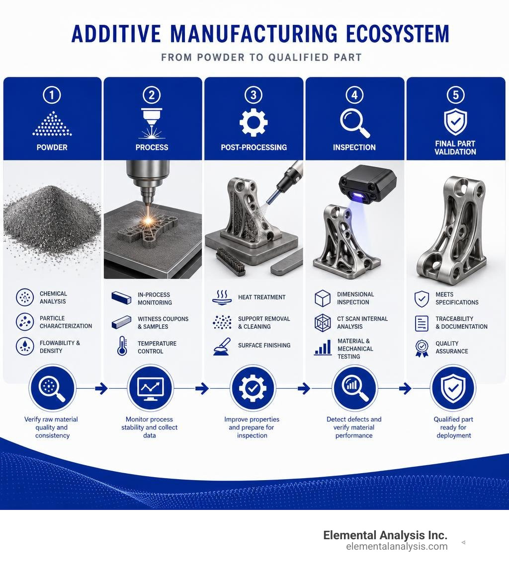
Additive Manufacturing vs. Traditional Manufacturing: Material Properties and Testing Needs
Traditional manufacturing relies heavily on subtractive techniques (like CNC milling or turning) or formative techniques (like casting and injection molding). These processes start with bulk materials that have already undergone extensive thermo-mechanical processing. As a result, their material properties are highly uniform and predictable throughout the volume of the part.
In contrast, additive manufacturing (AM) builds components layer-by-layer directly from digital CAD data. This fundamental shift introduces distinct advantages, along with entirely new testing challenges:
- Improved Buy-to-Fly Ratio: In aerospace, the “buy-to-fly” ratio measures the mass of the raw material purchased versus the mass of the final finished part. Traditional machining often wastes up to 90% of the raw material as metal chips. AM dramatically improves this ratio, using only the material required to build the part, plus a small amount for support structures.
- Design Freedom: AM enables complex geometries, internal cooling channels, and lightweight lattice structures that are physically impossible to machine.
- Material Uniformity and Process Variables: When you print a part, you are not just shaping the material; you are creating the material at the exact same time. The final microstructure, mechanical properties, and density depend entirely on localized thermal cycles, laser power, scan speed, and cooling rates.
Because of this, AM parts do not behave like their traditionally manufactured counterparts. The rapid melting and solidifying process creates highly complex microstructures that require dedicated material testing protocols. This need has driven massive growth in the AM material market, which expanded from $470 million in 2013 to over $1.09 billion in 2022.
| Material Property / Feature | Traditional Subtractive Manufacturing | Additive Manufacturing (AM) |
|---|---|---|
| Material Isotropy | Isotropic (uniform properties in all directions) | Anisotropic (highly dependent on build direction) |
| Buy-to-Fly Ratio | High (high material waste, up to 9:1 or more) | Low (minimal material waste, close to 1:1) |
| Defect Profile | Well-characterized bulk voids or inclusions | Process-specific voids, un-melted powder, delamination |
| Microstructure | Coarse/fine grains shaped by rolling, forging, or casting | Ultrafine, directionally oriented columnar grains |
| Testing Focus | Bulk mechanical verification | Microstructural, chemical, and orientation-specific verification |
How Additive Manufacturing Processes Affect Material Testing
The specific AM process you select directly dictates the types of material defects you must test for. Different thermal profiles, energy sources, and raw material feedstocks yield different structural characteristics:
- Direct Metal Laser Sintering (DMLS) & Selective Laser Melting (SLM): These powder bed fusion (PBF) methods use a laser to melt or sinter fine metal powders layer-by-layer. They require strict control over laser parameters to prevent “lack of fusion” voids or “keyhole” porosity.
- Electron Beam Melting (EBM): Utilizing an electron beam in a high-vacuum environment, EBM operates at higher build temperatures than laser-based systems. This reduces residual stresses but can yield coarser grain structures that affect tensile and fatigue performance.
- Selective Laser Sintering (SLS): Typically used for polymers, SLS sinters thermoplastic powders. Testing here focuses on powder degradation, thermal crystallization, and the degree of particle fusion.
- Material Extrusion / Fused Deposition Modeling (FDM): This process extrudes molten thermoplastic filaments through a heated nozzle. The mechanical performance of FDM parts is heavily dictated by molecular diffusion across the interface between adjacent beads.
Because each process introduces unique metallurgical or polymeric phases, choosing the right testing partner is critical. To learn more about how we verify raw materials and finished alloys, read our guide on How to Choose the Best Alloy Verification Laboratory for Your Projects.
Key Challenges in Additive Manufacturing Material Testing

Evaluating AM parts is not as simple as pulling a standard specimen on a tensile tester. The layer-by-layer nature of 3D printing introduces physical and mechanical complexities that complicate quality assurance:
- Anisotropy: This is the most critical challenge in additive manufacturing material testing. Because parts are built layer-by-layer, their mechanical properties are highly directional. The Z-direction (perpendicular to the build layers) is consistently the weakest link. Tensile strength, elongation, and fatigue resistance are typically lower in the Z-direction due to the risk of interlaminar delamination or poor interfacial fusion.
- Void Content and Porosity: Microscopic voids can form due to trapped gas in the raw powder, incomplete melting (lack of fusion), or unstable melt pools. These voids act as severe stress concentrators, drastically reducing fatigue life.
- Residual Stress: The rapid heating and cooling cycles inherent to AM create massive thermal gradients. As a layer cools and contracts, it pulls against the cooler layers beneath it, inducing localized residual stresses. If left untreated, these stresses can cause immediate warping, delayed cracking, or premature failure under external loads.
- Build Orientation and Raster Angle: The angle at which a component is oriented on the build plate directly influences its surface roughness, dimensional accuracy, and internal grain structures.
Standardizing Additive Manufacturing Material Testing for Polymers
While metal AM gets a lot of attention, polymer additive manufacturing is a massive sector. The photopolymer market alone grew from $239 million to $470 million in 2022. However, polymer AM parts face severe performance penalties compared to injection molding if they are not properly optimized and tested.
For example, in material extrusion (ME) of ABS, reductions in the elastic modulus can range from 11% to 37% compared to traditionally manufactured parts. However, research shows that ME-produced ABS parts can achieve approximately 80% of the strength of an injection-molded material simply by aligning the extruded beads directly with the loading direction.
Evaluating these properties requires specialized standards. To understand the current landscape of polymer testing, you can refer to the comprehensive Materials Testing Standards for Additive Manufacturing of Polymer Materials: published by NIST. This report highlights how traditional plastic testing standards fail to account for raster angles, air gaps, and bead-to-bead molecular diffusion.
Additionally, academic studies like Innovative Approaches to Material Selection and Testing in Additive Manufacturing emphasize the importance of managing filament storage and print bed temperatures to prevent moisture absorption and warping, which directly degrade a polymer’s mechanical limits.
Industry-Specific Testing Requirements
The rigor of your additive manufacturing material testing program depends entirely on your industry:
- Aerospace: Components like fuel nozzles, brackets, and turbine blades experience extreme static and dynamic loads. Testing focuses heavily on high-cycle fatigue, fracture mechanics, and absolute microstructural integrity.
- Medical Devices: The dental and medical AM market is expected to expand to $867 million by 2025, with the potential to reach $6 billion within 10 years as 3D-printed organs and tissues advance. For orthopedic and spinal implants, testing must verify biocompatibility, surface roughness (to promote bone ingrowth), and long-term fatigue life under physiological conditions.
- Automotive: Cost sensitivity is higher here, so testing focuses on rapid, high-throughput mechanical verification to qualify custom tooling, jigs, and lightweight brackets.
- Energy and Pressure Vessels: For components handling high pressures or corrosive fluids, testing must conform to strict structural integrity standards. The Standards Technology Bulletin (specifically ASME PTB-13-2021) outlines the first rigorous criteria for qualifying pressure-retaining metallic components manufactured via powder bed fusion.
Material Classifications and Specific Testing Considerations
The diverse range of materials used in AM requires a broad array of testing methodologies. Whether you are printing with advanced superalloys or high-performance polymers, the baseline chemistry must be verified. To learn more about how industrial testing labs operate, check out our guide on Elemental Testing Lab 101.
Common AM material classes include:
- Metals: Titanium (such as Ti-6Al-4V Grade 5), Nickel Alloys (Inconel 718/625), Stainless Steels (316L), and Aluminum Alloys. Testing must verify chemical composition, phase distribution, and interstitial elements (oxygen, nitrogen, hydrogen).
- Polymers: ABS, PLA, PETG, ASA, Nylon, and high-performance thermoplastics like PEEK or ULTEM. Testing focuses on glass transition temperature ($Tg$), melting point ($Tm$), and interlaminar shear strength.
- Composites: Carbon-fiber or glass-fiber reinforced polymers. Testing must evaluate fiber orientation, fiber-to-matrix bonding, and void content.
- Ceramics & Biomaterials: Alumina, zirconia, and bio-resorbable scaffolds. Testing focuses on density, micro-hardness, and biocompatibility.
The Role of Powder Characterization in Additive Manufacturing Material Testing
In powder bed fusion processes, the quality of the final part is directly inherited from the quality of the raw powder feedstock. If your powder is contaminated, has poor flowability, or contains internal porosity, your finished component will fail.
Powder characterization is the first line of defense in any QA program:
- Particle Size Distribution (PSD): Powders must have a specific size distribution to ensure they spread evenly across the build plate. Too many fine particles cause agglomeration; too many coarse particles lead to poor surface finish and low density.
- Chemical Purity and Contamination: Trace contaminants — even at parts-per-million (ppm) levels — can degrade the mechanical properties of reactive metals like titanium. Recycled powder must be monitored continuously for oxygen and nitrogen pickup, which cause embrittlement.
To identify these trace impurities with absolute precision, we utilize advanced spectroscopic techniques. For a deep dive into how we measure elemental composition, see The Ins and Outs of Inductively Coupled Plasma Mass Spectrometry and our article on What is Laser Ablation ICP-MS and How Does It Work?.

Critical Mechanical Properties and Standardized Testing Protocols

To qualify an AM component for structural service, several key mechanical properties must be measured using standardized ASTM and ISO methods:
- Tensile Strength & Yield Strength: Measured via ASTM E8/E8M (for metals) or ASTM D638 (for polymers). These tests apply axial force to a specimen until it fractures, revealing the material’s elastic limit, ultimate strength, and ductility.
- Elongation: Indicates the material’s ability to deform plastically before fracturing. AM parts often exhibit lower elongation in the Z-direction compared to wrought materials.
- Hardness: Measured using Rockwell (ASTM E18) or Vickers (ASTM E384) microindentation to verify that heat treatments have achieved the correct metallurgical hardness.
- Density: Because internal porosity is a constant threat in AM, verifying part density is critical. The Archimedean method (ASTM B311) is the industry standard for determining the density of powder metallurgy materials containing less than 2% porosity.
Failure Modes, Fracture Mechanics, and Fatigue Testing
Under cyclic loading, AM components are highly susceptible to fatigue failure. Microscopic surface roughness, un-melted powder particles, and internal gas pores all act as stress concentrators where fatigue cracks can easily initiate.
- Axial and Low Cycle Fatigue (LCF): Fatigue testing (ASTM E466 or ASTM E606) subjects specimens to repeated cyclic loads to determine the material’s S-N curve (stress vs. cycles to failure).
- Fracture Toughness: Measured via ASTM E399 to determine a material’s resistance to crack propagation.
- Aerospace Specifications: Rigorous specifications like those from the National Center for Advanced Materials Performance (NCAMP) govern critical aerospace alloys. For titanium, the NCAMP-DRAM specification (ND-ME-004) dictates strict fatigue and tensile testing requirements for Laser Powder Bed Fusion Ti-6Al-4V Grade 5 parts, setting minimum yield strengths (135 ksi) and ultimate tensile strengths (149 ksi) that must be met for flight qualification.
Equipment and Techniques for Mechanical Testing
Executing these tests requires specialized testing systems configured for the unique geometries of AM specimens:
- Servohydraulic Systems: Ideal for high-force dynamic and fatigue testing, capable of simulating millions of operational cycles.
- Electromechanical Systems: Best suited for high-precision, static tensile, compression, and flexural testing.
- Electrodynamic Systems: Perfect for low-force fatigue testing in clean or controlled environments, often utilized for medical device testing.
- Subscale Specimens & Custom Fixturing: Because extracting standard-sized ASTM specimens from finished AM parts is often impossible, we frequently use subscale specimens and custom fixtures to test actual part geometries.
Quality Assurance, Compliance, and Regulatory Standards
Achieving compliance in highly regulated industries requires strict adherence to consensus standards. The foundation of AM terminology and classification is governed by the standard ASTM F2792, which defines key processes like powder bed fusion, directed energy deposition, and material extrusion. Standardizing this language is essential for clear communication across complex supply chains, ensuring that manufacturers, testing laboratories, and end-users all operate under the same technical definitions.
For metal components, the joint standard ISO/ASTM 52908:2023 – ISO/ASTM 52908:2023 provides the definitive framework for post-processing, inspection, and qualification of powder bed fusion parts. It outlines the exact documentation, facility controls, and metallurgical tests required to certify finished parts for industrial use.
Witness Coupons vs. Direct Component Testing
When validating an AM production run, you have two primary options for testing:
- Witness Coupons: These are small, standardized test specimens printed on the same build plate, using the same parameters, and in the same orientation as the actual production parts. They undergo the exact same thermal post-processing. Destructive testing (tensile, fatigue, metallography) is performed on these coupons to infer the properties of the final parts without destroying the components themselves.
- Direct Component Testing: Involves testing the actual finished part. While highly accurate, it is often destructive and expensive. Non-destructive testing (NDT) methods like computed tomography (CT) scanning or ultrasonic testing are typically used on the actual components to inspect for internal voids and defect sizes.
The Building Block Approach to Qualification
To accelerate time-to-market while ensuring safety, we use the “building block” approach to qualify materials and components:
- Coupon Level: Characterizing raw material properties, baseline chemistry, and simple mechanical limits across various build orientations.
- Element Level: Testing simple structural features, such as joints, thin walls, or lattice cells, to validate design models.
- Subcomponent Level: Testing complex geometries extracted from or representing sections of the final part.
- Full-Scale Level: Subjecting the completed, finished component to real-world operational loads and environmental conditions.
This structured progression allows us to catch design and material flaws early in the R&D cycle, saving significant time and capital during final qualification.
Best Practices for Defining Test Requirements
When developing a quality assurance program for critical AM components, keep these best practices in mind:
- Engage with Standards Bodies: Align your QA workflows with standards developed by ASTM Committee F42 and America Makes to ensure regulatory compliance.
- Control Post-Processing: Thermal post-processing is mandatory for metal AM. Ensure your parts undergo Vacuum Stress Relief (VSR) to eliminate residual stresses before they are removed from the build plate.
- Densify with HIP: Utilize Hot Isostatic Pressing (HIP) to close internal pores and reduce anisotropy, bringing the material properties closer to wrought equivalents.
- Maintain a Process Control Document (PCD): Treat your qualified print parameters as a fixed, unalterable recipe. Any change in laser power, powder batch, or slice thickness must trigger re-qualification.
Frequently Asked Questions about Additive Manufacturing Testing
Why do 3D-printed parts require different testing methods than molded parts?
Molded or cast parts are isotropic, meaning their strength is uniform in all directions. 3D-printed parts are anisotropic and built layer-by-layer, which introduces unique microstructural interfaces, directional weaknesses (especially in the Z-axis), and process-specific defects like lack-of-fusion voids that traditional QA methods cannot detect.
What is the difference between 3D printing and industrial additive manufacturing?
While the terms are often used interchangeably, “3D printing” generally refers to rapid prototyping where parts do not experience significant mechanical loads. “Industrial additive manufacturing” involves robust, production-grade processes designed to manufacture end-use components that must meet strict safety, durability, and regulatory standards.
How does post-processing affect the mechanical properties of metal AM parts?
As-built metal AM parts contain high residual stresses and micro-porosity. Thermal post-processing, such as Vacuum Stress Relief and Hot Isostatic Pressing (HIP), is critical to relieve these stresses, close internal voids, refine the grain structure, and significantly improve tensile and fatigue performance.
Conclusion
As additive manufacturing continues to revolutionize industries from aerospace to medicine, the need for rigorous, scientific material testing has never been more vital. Navigating the complexities of anisotropy, powder chemistry, and evolving regulatory standards requires a testing partner who understands the molecular physics of these materials.
At Elemental Analysis Inc., located in Lexington, Kentucky, we provide the specialized analytical chemistry and material characterization services required to validate your AM workflows. As the first commercial Proton Induced X-ray Emission (PIXE) laboratory, we offer unmatched, non-destructive trace element identification, chemical purity testing, and rapid turnaround times to ensure your raw feedstocks and finished parts meet the highest standards of safety and performance.
To learn more about our advanced analytical techniques, read:
- The Ultimate Guide to Particle Induced X-Ray Emission
- How to Characterize Nanomaterials Without Losing Your Mind
- X-Ray Fluorescence Spectrometry Explained Simply
- The Ultimate List of Practical XRF Applications
Ready to secure your supply chain and accelerate your time-to-market? Learn more about NAA services and discover how our Lexington-based team can support your additive manufacturing quality assurance program today.